In our seventh installment of our retaining walls feature, Nick Liefting takes us through the complexities of gravity retaining walls.
Crib Wall
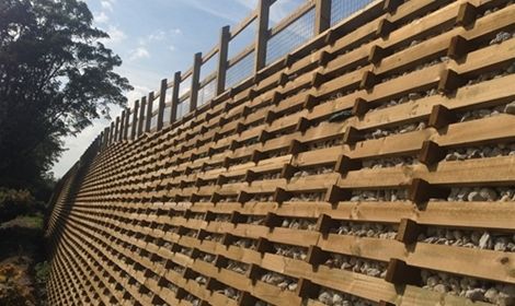
A crib wall is one of the oldest forms of retaining, which is, in simple terms, concrete or timber members criss crossing, coupled with large aggregate fill and a very generous lean back.
In all the years I have been constructing gravity retaining walls, I have never seen a failed crib wall. Yes, I have seen broken and dislodged retaining members, but never a wall that has actually failed. I believe this is due to two very important factors, which I will touch on in this article.
Crib walls are gravity retaining walls, constructed from interlocking, precast concrete components, or timber components. They are filled with free draining material and earth back-fill to eliminate the hazards of hydrostatic pressure build-up behind the wall.
The open web construction and use of free-draining material, eliminates two common causes of failure in retaining walls, namely hydrostatic pressure build up and the destructive pressure of tree root systems.
These walls are incredibly flexible and can easily be constructed to follow gentle curves, slopes, undulating terrain and around corners. The ability to dismantle and re-erect components quickly and easily as required, means crib walls may form temporary or permanent structures as the need dictates.
Footing preparation
As this is a gravity wall and depending on height, there is, and can be, a very high vertical ground loading, therefore a high KPA factor is required. However, a Geotech report coupled with an engineer’s design, will determine whether this type of wall is feasible.
Footing construction
As the retaining wall has a four vertical to one horizontal (4:1) lean back, this needs to be applied to the footing. The ideal footing is reinforced concrete, accurately screeded to grade and level, to avoid any imperfections whilst installing the wall units. See table below regarding different wall heights.
| Wall height | 1.20m | 1.80m | 2.40m | 3.00m | 3.60m | 4.00m | 5.00m |
| Footing width | 0.80m | 0.80m | 1.40m | 1.60m | 1.80m | 1.90m | 2.00m |
| Footing thickness | 0.20m | 0.30m | 0.40m | 0.40m | 0.50m | 0.50m | 0.50m |
Wall construction
There are only two different components to build the wall, which makes it simple.
Header
This is what is placed on the footing first, at 90° to the wall line. It is very important when positioning the headers as they determine the final position of the top of the wall.
Stretcher
This is what is placed in a notch at the front of the header and the back of the header, and runs along the wall line at 90° to the header.
As the wall increases in height, a large aggregate material is placed inside the crib units. It is best gently placed with an excavator, as we do not want any movement in the crib wall units as they are struck with the aggregate.
As mentioned in my opening paragraph regarding why these walls are less likely to fail; the two main aspects are lean back and the free draining of any water, i.e. through the front of the wall.
Timber Crib
These walls are becoming increasingly more popular, and I must admit they are not as “backbreaking” as the concrete components. The timber is H5 pressure treated and comes with a 50-year guarantee against rot and termite attack. The service life is well in excess of that. Timber crib construction is much the same as for concrete crib.
One of the disadvantages of a crib wall is the 1:4 lean back, particularly with, and if, land is a premium.
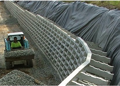
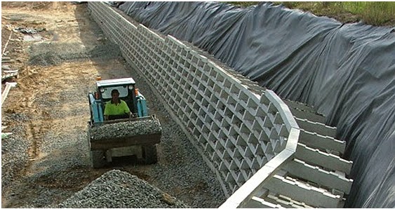
MSE Wall
This stands for mechanically stabilised earth, and also involves another form of wall: RSS (reinforced soil slopes).
Both types of walls are almost identical in construction, except that the MSE wall has a veneer facing, for aesthetics only. These walls can be constructed to almost vertical.
- A Tensar or Geogrid is placed horizontally
- Good compactable fill is placed on top to a maximum thickness of 300mm, and well compacted
The MSE wall, as mentioned, has a veneer facing which is generally concrete panels of various aesthetic designs. These are fitted with brackets behind, and are fitted to ribbed reinforcing strips preset in the compacted earth layers.
These walls do not have a drainage blanket at, or near to, the face, but as I have always maintained, drainage is paramount. The drainage is installed as a trench filled with drainage metal, which is placed behind the Tensar/Geogrid. At the base of the trench, a drain-coil is placed with 90° tee-offs leading out under the compacted fill to the front of the wall. It is best to install this as the height increases.
As this can be a relatively easy wall to construct, I would still strongly emphasise the importance of having an engineer do the design, which is necessary over 1.50m high anyway, or lower if indeed there is a surcharge.
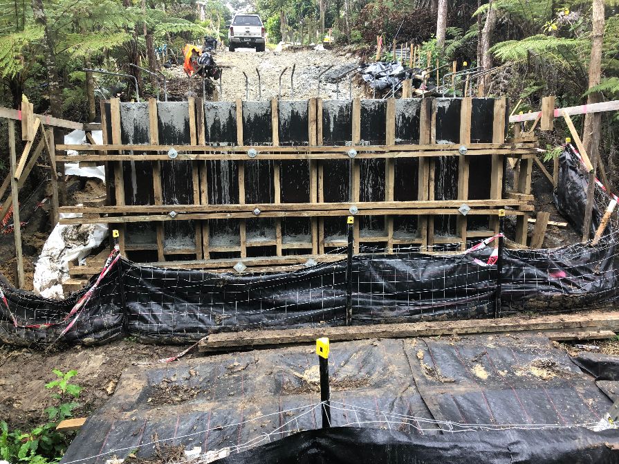
Concrete Walls
By concrete walls, I mean cast-in-situ concrete walls. The foundations for these walls are much the same as for a masonry wall.
Wall construction
Cast-in-situ walls are capable of being higher than masonry walls, due to the fact that even with a 250 series block (250mm wide), it only gives a 180 thick block fill. Masonry blocks are only a veneer and do not contribute greatly to the integral strength of the wall. It is also difficult to have a double layer of vertical reinforcing. Once block fill is placed, it cannot be vibrated, as it would blow the blocks apart.
Process of wall construction:
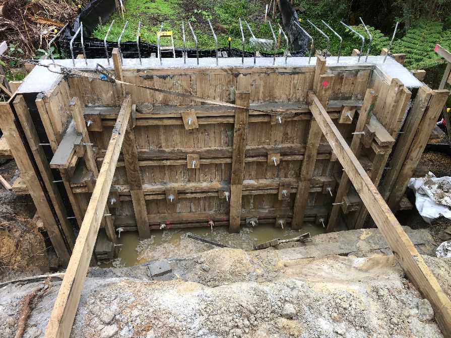
- As with all concrete work, we need to install boxing, which is a term mainly used for pathways, house slabs, etc. Once cast-in-situ work is carried out, the term we use is formwork.
- Shutters are generally constructed prior to arriving. These are made using a 17mm form-ply with a 100×50 or 150×50 (depending on height) frame, at 400mm centres.
- Form-ply is a black colour and is specifically produced for just that. Upon removal, it leaves no imperfections (grain, knots), left by normal ply. Before installing, coat the shutters with form release agent. This makes for easy removal.
- These shutters are bolted onto the concrete slab and also nailed together. It is best to carry out this work on the retained side of the proposed wall.
- Horizontal walers, e.g., 150×50, are attached along the length of the wall to the back of the shutters. There are two walers at 50mm apart.
- The lower walers will be close to the concrete footing and spread further apart up the wall.
- Brace the top of the shutters to the back of the concrete footing, creating a plumb and straight line.
- Between the walers, drill 16mm holes. These holes are closer at the bottom, and the spacing can increase as we go up the wall.
- Say, for example, the concrete is to be 200mm thick, cut 200mm lengths of 20mm PVC and with 1.00m x 16mm threaded rods, place these through the PVC and on through the reinforcing steel and between the walers.
- Now repeat the process for the front formwork. The bracing will not be necessary.
- With the 16mm threaded rods, place a large (100mm x 12mm thick) square washer against the walers and tighten.
- To help with aesthetics once the forms are released, fasten a 45° beading along the top and in any (what will be) visible corners.
- Place concrete – the concrete is generally pumped and is important to be adequately vibrated.
- For walls greater than 2.40m high:
– This will require additional shutters vertically.
– Once this happens, we have what we call soldiers, which are vertical timbers, similar to the walers, to keep the shutters in a vertical alignment.
– Formwork must remain in place for at least three days before removal.
– Once shuttering is removed, the PVC conduits are easily tapped out of the fresh concrete.
– These holes can then be filled with an approved epoxy.
It is also important to know that concrete can only be placed in 1.20m lifts along the wall and vibrated, then going back to the start and with another 1.20m lift, up to 3.60m maximum. If there is more height, this can then resume the following day.
I have done a lot of concrete formwork, having used many different methods of formwork/shuttering etc, and have learnt waler and tie bar spacings from experience.
A Structural Engineer will happily do a formwork design for you if you are not so sure. I have always over-waled and over-tie bared, but have never had a formwork failure. When that vibrator hits the concrete, you can certainly hear all the creaking and groaning of the formwork!
For your information, with a 2.40m height and 200mm thick concrete, there is in excess of 10 Tonne horizontal load at the base of that 1.20m wide shutter.
Article provided by Nick Liefting
www.nlcontractors.co.nz![]()
Published in Training & Events in WIRED Issue 71 / December 2023 by Fencing Contractors NZ
Read WIRED online
Follow us on Facebook
© Fencing Contractors Association NZ (FCANZ)
Read the other articles here: